
Installing GRC Board involves far more than screwing the board to a metal profile. A successful mechanical clinker façade requires the existing substrate, anchor design, insulation and moisture layers, profile grid, board joints, clinker bonding and grouting to be treated as one system.
The sequence below describes a general installation approach. Bracket section, anchor type, profile spacing, screw layout and movement-joint locations must be determined by specialists according to the project’s structural and architectural conditions.
1. Survey and collection of project data
The first step is to measure the façade and identify the load-bearing substrate. Reinforced concrete, brick, pumice block and aerated concrete do not use the same anchoring solution. Façade height, building location, openings, corners and existing wall deviations are recorded.
- The net façade area and door/window openings are measured.
- The wall’s plumb and plane are checked.
- Wind load and anchoring capacity are assessed.
- Sill, parapet, drip and drainage details are drawn.
2. Brackets and subframe
Project-suitable L-brackets are fixed to the primary structure, and vertical support profiles are connected to them. Bracket length is selected by considering insulation thickness, the required air cavity and façade adjustment allowance together.
Correct use of fixed and sliding connections reduces stresses caused by thermal movement. Because a small deviation in the profile grid becomes amplified and visible across the clinker courses, plane checks are repeated throughout installation.
3. Insulation and moisture management
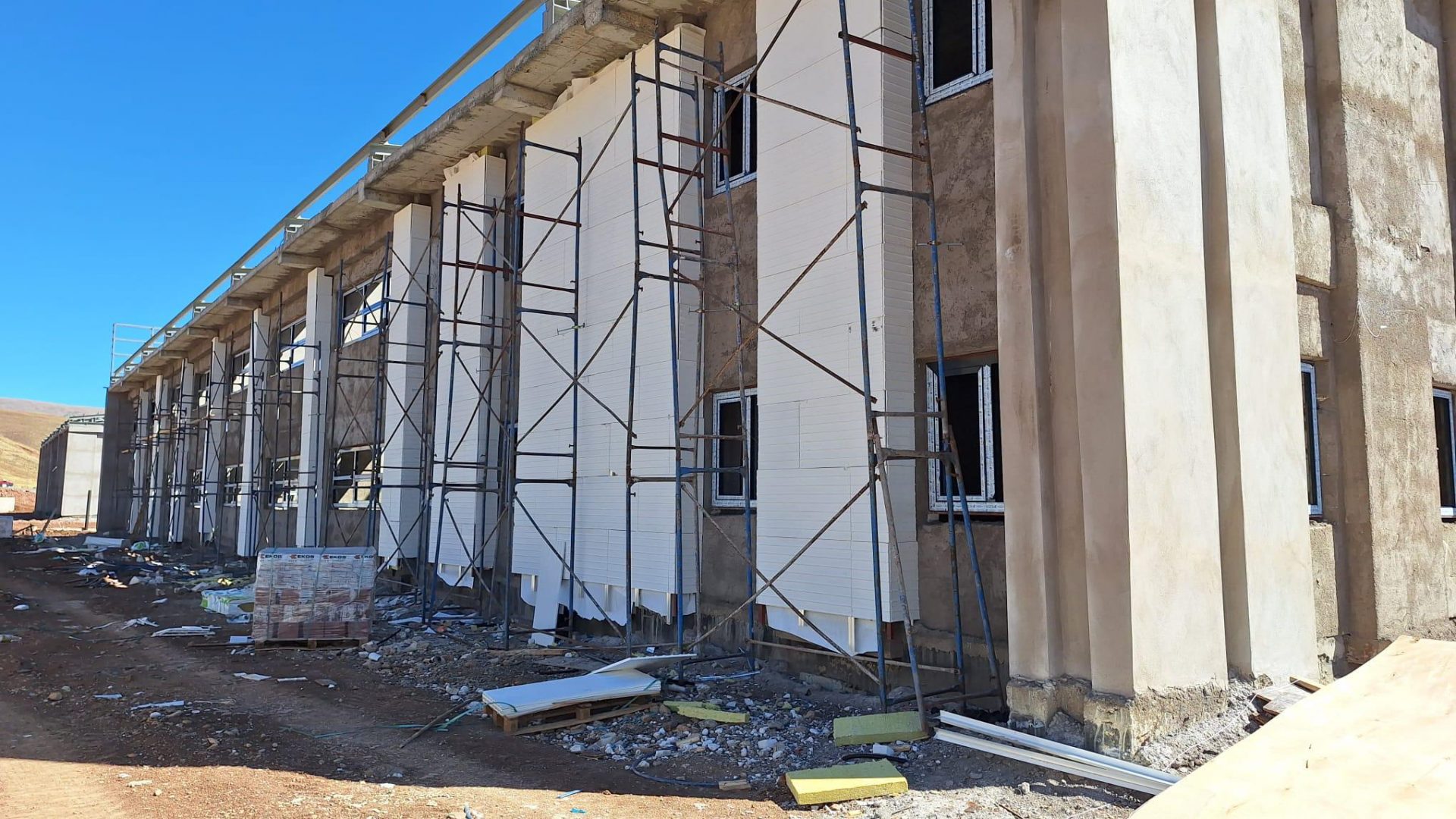
Where thermal insulation is specified, mineral-wool boards are fixed to the substrate with an appropriate anchor pattern. Moisture membrane joints are lapped and continuity is secured with tapes. Bracket penetrations, window surrounds and horizontal terminations are detailed to prevent uncontrolled water entry behind the system.
If sill, parapet and drip details are considered only after cladding is complete, persistent problems may develop at joints and corners. These points must be resolved before installation.
4. Fixing the GRC Board sheets
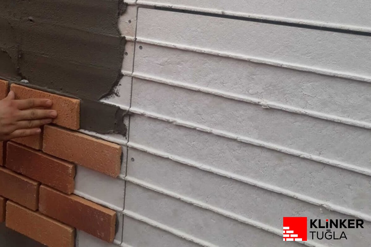
The 605 × 1250 mm brick-grooved GRC Board sheets are positioned so that joints remain over supporting profiles. Gaps between boards follow the manufacturer’s requirements, and screw heads are tightened without crushing the board. Edge distances and screw spacing are maintained.
- The bottom starting line is levelled.
- The first board is positioned to suit the profile grid.
- Joint gaps and vertical alignment are checked.
- Cut edges are cleaned, and no unsupported joint is left.
- Movement joints are continued in accordance with the architectural details.
5. Clinker brick installation
Dust and loose material are removed from the board surface. A system-compatible C2TE-class flexible adhesive is prepared and used within its working time; where required, it is combed onto both the substrate and the back of the brick. Bricks are positioned using the board grooves as a guide.
For products with natural colour variation, blending bricks from different boxes reduces unwanted colour blocks on the façade. Horizontal and vertical joints are checked at regular intervals.
6. Grouting, cleaning and final inspection
Once the adhesive has set sufficiently, joints are filled continuously. Grout consistency, depth and finish affect water management as well as the façade’s appearance. Material on the brick face is cleaned by an appropriate method before it sets.
The final inspection covers loose elements, unfilled joints, cracks, staining, drainage details, corners and returns at openings. Horizontal and vertical lines across the façade are reviewed again before project handover.
The most common on-site mistakes
- Starting installation without checking the load-bearing substrate and anchoring capacity.
- Failing to plan the profile grid around the board dimensions.
- Leaving a board joint unsupported or overtightening screw heads.
- Using an unsuitable adhesive or exceeding its open time.
- Neglecting movement joints, sills and drainage details.
- Proceeding with the whole façade without a mock-up area.
THE DIFFERENCE THAT SAVES TIME ON SITE
No separate spot-fixing stage: position the board and screw-fix it directly
One of the first questions installation teams ask us is: “When the board arrives on site, do we still have to drill the fixing points and prepare it with an extra spot-fixing operation?” With our GRC Board solution, no separate spot-fixing preparation is required.
Some GRC boards may require their fixing tabs to be drilled and prepared on site before installation. Our board contains a continuous, one-piece alkali-resistant reinforcing mesh throughout its body. Subject to the approved design and screw pattern, it can be screw-fixed directly through its tabs or through the fixing points defined in the project.
Pre-drilling and spot-fixing add labour and coordination to every panel; on some sites, two or three people may be needed to prepare and place one panel. Direct screw fixing removes that intermediate step, helping a two-person team position boards more comfortably and maintain a faster installation rhythm. Actual output depends on the project detail, access and site conditions.
What does the 13+5 mm section provide?
Our product has a 13 mm backing and a 5 mm channel pitch, giving an overall section of approximately 18 mm. This geometry provides a consistent reference for clinker courses, while the continuous mesh supports a controlled structure at the fixing points. The final screw pattern and rail centres must be verified for every project by structural calculation and current manufacturer documentation.
A written warranty criterion for the clinker
For the Ateş Tuğlası clinker products supplied with the system, we require a 10-year written manufacturer warranty covering colour stability, resistance to efflorescence and frost resistance. The exact scope, product range and project conditions are confirmed against the current warranty document at quotation stage.